_副本")
Description
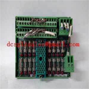
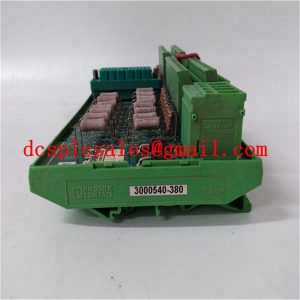
IC698CRE030-EE Water Pump Inverter
IC698CRE030-EE contactors K1, K2, K3 make the pump work in the industrial frequency state, while K4, K5, K6 are connected to the inverter output to make the pump work in the inverter state, taking into account that each pump can not work at the same time in the industrial frequency and the inverter state, the electrical equipment is used to protect the contactor interlock. Initial state, the inverter output is connected to the first pump motor, the network pressure rises, when the pressure is less than the given value, the need to add pumps, the relay output port from the inverter sends a signal to the PLC, the PLC control switching process.

When the IC698CRE030-EE inverter stops output (the inverter is set to free stop), the inertia of the pump is used to switch the first pump to IF operation, the inverter is connected to the second pump to start and run, and so on, the second pump is switched to IF operation, the inverter is connected to the third pump to start and run.

When IC698CRE030-EE needs to reduce the pump, the system will stop the first pump and the second pump in turn, when the inverter is connected to the third pump. This approach ensures that there will always be a pump in frequency operation, any one of the three pumps may be frequency operation. In this way, in order to do regardless of how the water consumption can be changed to maintain a basically constant network pressure, and the pumps running time is basically the same, which brings convenience to the maintenance and overhaul, and improve the service life of the system.