_副本")
Description
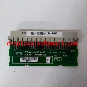
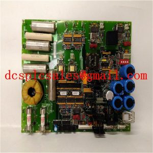
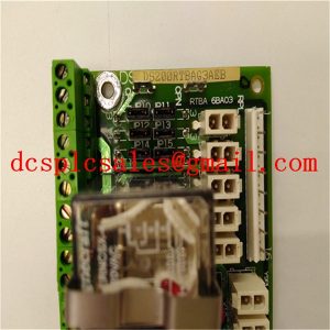
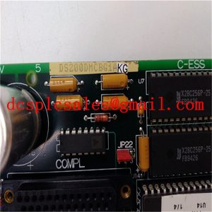
GE IC660ELB912 Network Interface Board
GE IC660ELB912 Under normal circumstances, motor M1 is in frequency conversion speed regulation state, and motor M2 is in shutdown standby state. The on-site pressure transmitter detects the outlet pressure of the pipe network (4-20mA analog signal) and compares it with the predetermined value, which is calculated by the special PID instruction inside the PLC to get the frequency signal required by the frequency converter, and then adjusts the speed of the motor automatically to achieve the required pressure of the pipe network.

GE IC660ELB912 Press the “stop button”, PLC control all contactors disconnect, inverter stop working. When it is necessary to switch from motor M1 to M2, contactor KM2 will be disconnected and KM1 will be closed, at this time, motor M1 is working at working frequency, after the inverter stops completely, KM4 will be closed, the inverter will restart, and motor M2 will start under the drive of the inverter; after the inverter has started completely, KM1 will be disconnected, motor M1 will stop, and the switching operation will be finished. The process of switching motor M2 to M1 is similar.

GE IC660ELB912 sets alarm and interlock protection through the internal program of PLC, so that the corresponding operation will be stopped and alarm will be given once a fault occurs. For fault self-diagnosis function, taking into account the cost of the problem, did not design the host computer, only set the corresponding fault code, through the 4 digital tube display, so that maintenance personnel can be based on fault information to facilitate the search to the point of failure. For example: (a) low compressor oil pressure, low water pressure and other fault signals can be measured by the field explosion-proof electric contact pressure gauge, sent directly to the PLC, controlled by the PLC to realize the sound and light alarm and delayed stopping; (b) the addition of on-site vibration sensors, and the signal will be sent to the PLC, the compressor operating conditions for display and diagnosis.