Description
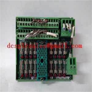
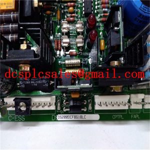
DS200DCFBG1BLC Common Cathode Digital Tube
DS200DCFBG1BLC In order to ensure the display brightness of the digital tube, two pieces of 74HC245 to realize the digital tube drive. One 74HC245 is used to drive the segment code of the 4-bit common cathode digital tube, its input is connected to the P0 port of the microcontroller, and its output is connected to the 8 segment code pins of the 4-bit digital tube after current limiting resistor. Another piece of 74HC245 drive the bit code of 4-bit digital tube, its input and the microcontroller’s P1.0 ~ P1.3 connection, the output is connected to the common terminal of the 4-bit digital tube.
DS200DCFBG1BLC realizes data transmission by occupying two output points of PLC, which are used as data line and clock line respectively. Because the display data transmission is serial, so must design the corresponding transmission timing. When constructing the transmission sequence of both sides, the working principle of the PLC system, the output characteristics and their differences, as well as the reliability of the transmission process must be fully considered. The transmission sequence designed after considering these factors is shown in Figure 4.
The DS200DCFBG1BLC requires a total of 21 clock cycles to transmit one display data, of which 3 clocks are used for the synchronization signal, 16 clocks are used to transmit the 4-digit BCD code of the display data or a specific prompt character, and 2 clocks are used to transmit the 2-digit information that indicates the display position of the decimal point. The lower bits of the display data and the decimal point position information come first and the higher bits come second. For example, FIG. 4 indicates that the transmitted display data is 8951 and the decimal point position information is 10, indicating that the decimal point is after the tenth digit, so the final display data is 895.1.


