Description
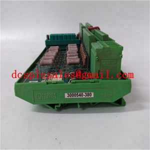
ALSTOM N897164610LPulse Output Module
ALSTOM N897164610L may temporarily lose speed for various reasons. To avoid malfunctions as a result, a built-in time delay is provided. The output relay will exit after a preset time delay after the speed has dropped below the set value. If the unit regains speed during this period, the relay continues to hold. Speed sensors and zero speed switches are used to protect equipment, processes and personnel. When the speed sensor or speed switch detects a change in speed, a signal is sent to the control panel or alarm to alert the operator of a malfunction. When an alarm is triggered, steps can be taken to correct the problem before catastrophic failure occurs. This greatly reduces your downtime, maintenance costs, and material waste costs. Operational life is also maximised without the risk of unplanned failure. The module is used to monitor the speed of industrial machinery such as conveyors, crushers, mills, mixers, blenders, agitators, screw conveyors and more. The device activates relay contacts at a preset speed. Using these contacts, desired control actions such as zero speed protection/low speed protection/over speed protection can be realised. It senses the speed in a non-contact way. Therefore there are no moving parts.No roller wear or joint inconsistencies.Simple speed setting.Built-in initial bypass time delay arrangement. Selectable range of 1 to 5000 revolutions per minute.Completely enclosed sensor that works with dust, dirt water, oil and chemicals.Direction sensing and speed monitoring can be carried out at different locations from a single point.Built-in safety sensor and speed switch with fire ring for use in hazardous areas. The combination of engineering expertise and automated conversion tools made it possible to generate the Deltav operator interface displays using the same key objects, layouts and toolbars for one-click navigation of the other displays. Using the 140CPU67160 significantly reduces the time, effort and risk associated with display development.” Our operators appreciate the Deltav system’s user-friendly interface, workstation functionality, screen management, ease of use of the alerting and trending tools, and automated report generation and manual report generation tools
The database conversion for the ALSTOM N897164610L generated 100% of the modules required to connect to the solution interface. All conversions were supervised and checked. This process, especially the automated conversion tool, greatly reduced the chance of errors during interface configuration. Deltav’s simulation capabilities provided an on-site, multi-node training system to familiarise operators with the process before it went online. This ensures that changes are made as smoothly and efficiently as possible. To handle the critical range of total inputs and outputs, Emerson installed two redundant servers with Deltav connection licences, each with 10,000 tags. Most flow measurement techniques cannot achieve satisfactory measurement linearity from maximum rated flow all the way to zero flow, regardless of how well they are matched to the process application. In addition, the performance of most flowmeter technologies is critically dependent on proper installation. One cannot simply hook up a flow meter anywhere in the pipework and expect it to function as designed. This is a source of constant friction between piping (mechanical) engineers and instrumentation (control) engineers on large industrial projects.Piping layouts that can be considered excellent from the standpoint of process equipment functionality and economics are usually (at best) poor for good flow measurement and vice versa. In many cases, flowmeter equipment is not properly installed and the instrumentation technician must deal with the resulting measurement problems during start-up of the process unit. Even where a flowmeter has been properly selected for a process application and properly installed in a pipeline, problems may arise due to variations in process fluid properties (density, viscosity, conductivity) or the presence of impurities in the process fluid.


