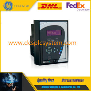
Description
560CMU05 Collect and convert data on site
After the on-site signal is accurately input to the PLC, the PLC executes the program and adjusts and controls the on-site device through the execution mechanism. How to ensure that the executing agency works according to control requirements, and how to detect faults when the executing agency does not work as required? We take the following measures: when the load is controlled by the contactor, starting or stopping this type of load is converted to controlling the contactor coil. We are concerned about whether the contactor is reliably engaged when starting and whether it is reliably released when stopping.
The X0 of 560CMU05 is the contactor action condition, Y0 is the control coil output, and X1 is the contactor auxiliary normally open contact that is led back to the PLC input. The timer timing time is greater than the contactor action time. R0 is the set fault position, and R0 is ON, indicating a fault and performing alarm processing; R0 is OFF, indicating no fault. The fault has a memory function and is cleared by the fault reset button. When 560CMU05 opens or closes the electric valve, a delay time is set according to the different opening and closing times of the valve. After the delay detection, the signal of opening to the position or closing to the position is detected. If these signals cannot be accurately returned to the PLC on time, it indicates that the valve may have a fault, and a valve fault alarm should be processed. X2 is the valve opening condition, Y1 is the control valve action output, the timer timing time is greater than the valve opening in place time, X3 is the valve in place return signal, and R1 is the valve fault position.


