_副本")
Description
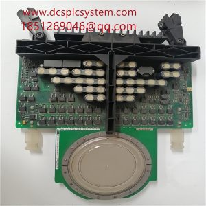
3BHE022294R0101 3BHE020356R0101 GF D233A Auxiliary Contactor
3BHE022294R0101 3BHE020356R0101 GF D233A can basically meet the requirements by adopting the dual-loop control with frequency conversion speed regulation. While using the existing rotary encoder to form the speed loop, the number of pulses proportional to the speed of the motor and the displacement of the lift is output through the PG card of the frequency converter and is introduced into the high-speed counting input port of the PLC, and the pulse equivalence is calculated through the cumulative pulse count by Eq. The pulse equivalent is calculated, from which the lift position is determined.

3BHE022294R0101 3BHE020356R0101 3BHE020356R0101 GF D233A When the lift is directed upwards, the upward direction relay, the express car auxiliary contactor, the express car running contactor, the door lock relay, and the upward travelling contactor are electrically absorbed, the holding brake opens, and the lift travels upwards. When the car touches the upper forced speed change switch, the PLC internal latching relay is electrically activated, and the timer Tim10 and Tim11 start timing, and the duration of the timing can be set depending on the floor distance of the end station and the ladder speed.

3BHE022294R0101 3BHE020356R0101 GF D233A After the operation of the forced speed change switch, the lift will be changed from fast car operation to slow car operation, and the lift should be parked when going up to the level under normal circumstances. If the car does not stop and continues to go up, when the setting value of Tim10 is reduced to zero, its normally closed point will be disconnected, the slow car contactor and upward contactor will be de-energised, and the lift will stop running. After the car touches the upper forced speed change switch, the lift fails to turn to slow car operation due to some reasons, and the fast car operation contactor fails to release, and its normally closed point breaks when the set value of Tim11 is reduced to zero.