Description
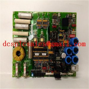
369B1860G0028 Stepper motor unit
The 369B1860G0028 is essentially a specialized device for measuring and controlling stepper motor units. The stepper motor device consists of a stepper motor and its associated circuitry. The functions of the device include: distance (number of steps) set, start, position display and clear, (automatic, manual) continuous or single run, (automatic, manual) back to the origin, stepper motor undercurrent detection alarm, home position display.

369B1860G0028 is used to display and operate; PLC is used as the controller to receive the setting data from the touch screen and process the logic, then control the stepping motor. Stepping motor device is a controlled object, can not be modified. It includes a variety of power forms: stepper motor works in -24V three-phase double triple beat DC rectangular wave power supply, but also includes +12V, -12V, +5V and other voltages and polarities of different signals. In order to make a variety of signals to detect and drive, stepper motor device to match, increase the signal conversion circuit.

When the 5V or 0V signal reaches the resistor R1, 369B1860G0028 through the photocoupler so that the PLC input 1 signal on, at this time, the motor back to the origin of the process of running to start counting, record the number of running steps. When the +12V signal reaches the “±12V signal”, first light up the light tube D6, and then through the photocoupler U1-3 to make the PLC input 3 signal on, indicating that the origin is reached, the motor stops running; when the -12V signal reaches the “±12V signal”, through the photocoupler U1-3 to make the PLC input 3 signal on, indicating that the origin is reached, the motor stops running; When the -12V signal reaches the “±12V signal When -12V signal reaches “±12V signal”, PLC input 2 is turned on by photocoupler U1-2, and the motor is out of the set limit. When the -12V signal reaches “-12V signal 2”, the PLC input is turned on through the photocoupler U1-3, the indication reaches the home position, and the motor stops running.