Description
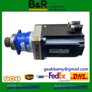
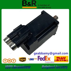
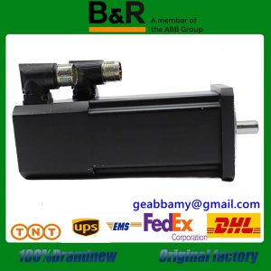
7AO352.70 Servo Positioning Unit
7AO352.70 in the cutting process has a good control of pressure, cut into the amount, according to different glass materials should be set to different pressure and cut into the amount, in addition to cut off the steps are more important, generally used steps are: ① CF surface cut ② TFT surface cut ③ TFT surface cut ④ C F surface cut. In the scribing equipment are now used in the multi-knife (previously a single knife work), generally in the 5-7 knives, this system uses 5 knives, in this system the knife’s cut into the amount of left and right movements are controlled by servo systems, and are used in high-speed movement, which can greatly improve the efficiency of the work.
The 7AO352.70 uses the Q06H CPU as the control unit and the IOP310 as the positioning unit of the servo system. Two IOP310 communication module units are also used, one of which is connected to the HMI (A970GOT), and the other is connected to the image processing system, which is mainly used for the identification of Mark points (i.e., marking points), and then produces a deviation correction value. The other one is connected to the image processing system. In addition, the PC1 connected to the QJ74C24 is a special machine for setting the mechanical parameters and working parameters of the system as well as programming the cut-off procedure.
The communication of the 7AO352.70 is carried out using a special communication programme software. This system works by using deviation correction. For a new variety, the first Mark point recognition, login, MARK point shape can be arbitrary, but the general use of the word ‘ten’ for the Mark point marking, as shown in Figure 4, is the image processing system on the Mark point recognition process, recognition after the generation of a deviation from the amount of correction, based on the amount of deviation from the calculation of the reference position.


